Contents
| Magnetic property characteristics measurement system |
| per01002050701-01 |
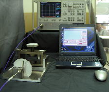 KEYCOM’s magnetic property characteristics measurement system delivers ideal measurement solutions for complex permeability μr'- jμr'', ferromagnetic resonance relaxation coefficient α, resonant line width ΔH, and saturation magnetization 4πMs in wideband from 100kHz up to 14GHz. KEYCOM’s magnetic property characteristics measurement system delivers ideal measurement solutions for complex permeability μr'- jμr'', ferromagnetic resonance relaxation coefficient α, resonant line width ΔH, and saturation magnetization 4πMs in wideband from 100kHz up to 14GHz.Its simple measurement process of setting your disk or square specimen on the microstripline and sweeping the frequency with your vector network analyzer makes your measurement easier and more accurate. |
| S-parameter method Reflection and transmission mode coaxial tube and waveguide type dielectric constant, dielectric loss tangent, permeability, measurement system |
| dps08002011118-07 |
| This measurement equipment enables 2 different kinds of measurement methods of the reflection and the transmission, one of which can be chosen depending on the purposes. Either method makes it possible to measure complex dielectric constant and complex ur at the same time. How to select one of the 2 methods is as follows. Also an absorption ratio and a reflection ratio of the electromagnetic absorber can be obtained by calculating complex dielectric constant and complex μr. |
| S-parameter method Free space type reflection mode for flat plate dielectric constant and permeability measurement system |
| dps09002981027-08 |
| Unlike the coaxial-tube-type or a waveguide-type methods, this method does not involve errors caused by air-gaps since the specimens are not installed in a fixture. Practical data can be obtained even when the specimen is placed on a rough, uneven surface. It is compact and allows specimens to be measured by flat-wave because of the direct installment of lens with an antenna. It performs measurements by monitoring the S11 parameter via connections of a test fixture to a vector network analyzer and a PC. |
| S-parameter method Free space type transmission mode for flat plate dielectric constant and permeability measurement system |
| dps21002040614-08 |
| Unlike a coaxial tube type or a wave guide tube type, this method does not make errors caused by air-gap because specimens are not put into a fixture. Practical data can be obtained even at the rough, uneven surfaces where the specimen is placed on. It enables compactness and measuring specimens by flat-wave because of direct installment of lens with an antenna. Measurement is achieved by monitoring S21 & S11 parameter with connections of a test fixture to a vector network analyzer and PC. |
| Angle of incidence change method, dielectoric constant, dielectric loss tangent, permeability measurement system |
| dps22002040516-08 |
| It can be measured the dependency on angle of incidence of the magnitude and phase of the reflection coefficient in both the TE wave and the TM wave. Complex relative permittivity and complex permeability are estimated from these measured values. Unlike the coaxial-tube-type or a waveguide-type methods, this method does not involve errors caused by air-gaps since the specimens are not installed in a fixture. The lens attached to antenna enables to measure samples with plane wave, resulting in the high measurement accuracy. This method using a parallel beam from a antenna can reduce the size of a specimen. In all frequency range,. εr and μr can be obtained. |
| Eripsometore method, dielectric constant and permeability measurement system |
| dps02002051012-05 |
| Vector network analyzer is not required, as it is a scalar measurement. Dielectric constant compared with source and permeability compared with source can be measured the difference between TE TM wave of the reflection coefficient and amplitude ratio of the wave and phase. Unlike coaxial tube or waveguide, and the error by the airgap doesn't occur as it doesn't put the sample in Ficscha. It is compact size installing a lens to an antenna. You can measure a sample by plane wave. As the sample can be set close to the antenna, the sample will be small in size, you can read εr' and μr at frequency. |