- HOME
- Radar Cross Section (RCS) Measurement and Evaluation System
Radar Cross Section (RCS) Measurement and Evaluation System
Model No. XRC
Keycom fully utilizes its advanced millimeter-wave and microwave system development ability to develop a variety of radar and radar test systems.
Along with standard radar targets, Keycom also offers a variety of systems that can accurately measure the radar cross section (RCS) of radar targets, such as aircraft, ships and automobiles.
If you have any questions or requests, please feel free to contact us!!!
👉E-mail:info@keycom.co.jp
【Related Contents】
👉For developing Radar(Microwave, Millimeter wave) in general : Please check here
👉For developing Automotive Radar : Please check here
1. Radar Cross Section (RCS) Measurement and Evaluation System
| |
1.1. Imaging Radar [RCS11] |
|
1.2. Approach Type RCS Measurement System [RAT08] |
| |
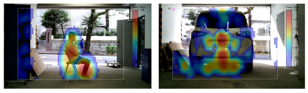
1.RCS (Radar Cross Section) measurement
- Creates images of reflection signals from targets of in-vehicle
radar almost in real-time.
2. Monitoring of intruder or moving target (perimeter monitoring option available)
3. Level gauge
4. Fluid flow analysis |
|
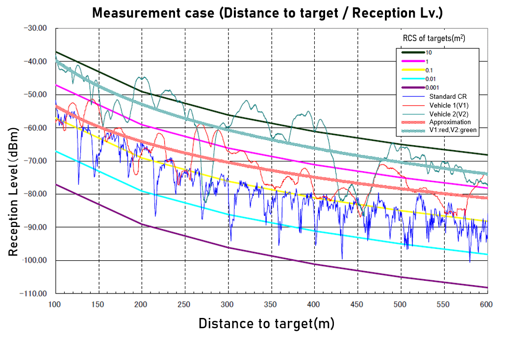
The system sends and receives pulsed waves as it moves toward the target whose RCS you want to measure.
It measures the RCS , and fits it to the radar equation to obtain correct value.
Through making several measurements by changing the position of radar or target, you can see how the multipath on the road surface affects the results.
It is also possible to set up a fence in the middle to measure, avoiding multipath effects. |
| |
Detail! |
|
Detail! |
| |
1.3. RCS Imaging Evaluation System [RAT06] |
|
1.4. Cylindrical type, Near/Far-Field Conversion RCS Measurement System [RCS03] |
| |
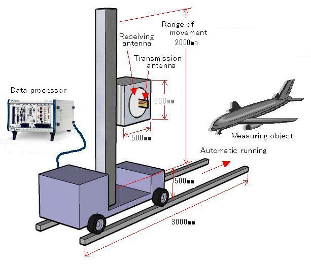
The visualization of the distribution of electromagnetic waves reflected
from machines and other objects can contribute to the improvement of
radiowave-absorbing materials and the shape of machines.
In addition, it is possible to compute the RCS for each part of the
system or for the entire system by performing synthesis considering
the phase of the reflected waves. |
|
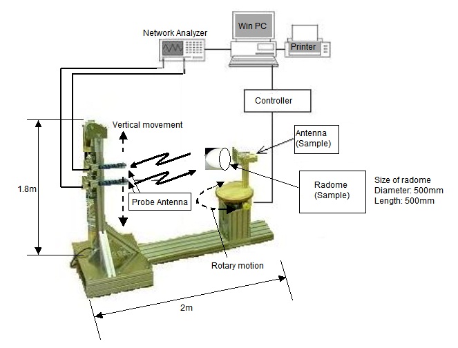
By combining the vertical movement of the two probe antennas with the rotational movement of measuring objects,it performs cylindrical near-field measurements and converts the measurement results into far-field. |
| |
Detail! |
|
Detail! |
| |
1.5. Compact Range, Near/Far-Field Conversion RCS Measurement System-01 [RCS01] |
|
1.6. Compact Range, Near/Far-Field Conversion RCS Measurement System-02 [RCS02] |
| |
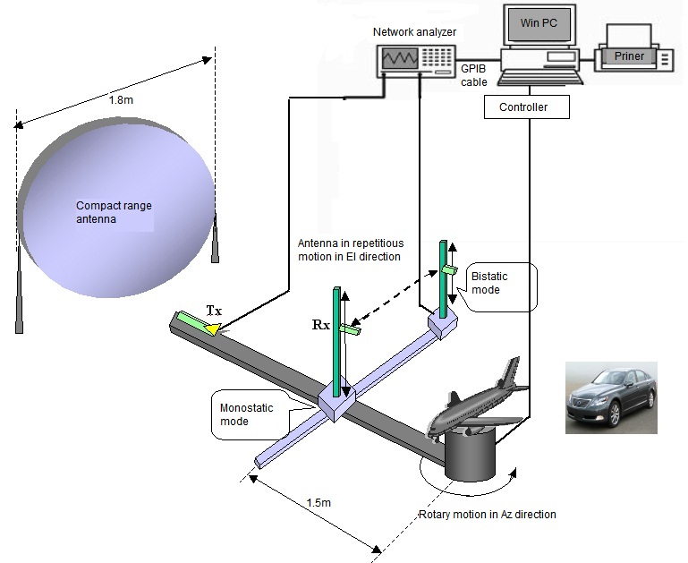
1. The measurement antenna attached to the mast that is movable in EI direction
receives the plane wave transmitted by the compact range antenna in
near-field after reflected by the target.
2. Rotary motion of the target in Az direction enables omniazimuth measurement.
3. Monostatic measurement is made possible when the receiving antenna
is placed in the center plane of the compact range antenna, and bistatic
measurement when the antenna is placed off the center plane.
4. Received data is converted to far-field mathematically to create
RCS and images.
·Not only monostatic but bistatic RCS can be measured by integrating
Cassegrain antenna. |
|
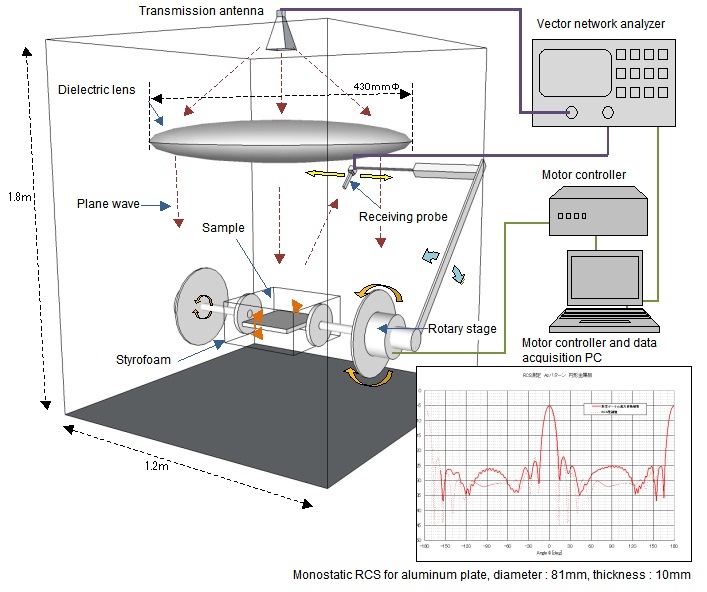
RCS02 irradiates a rotating sample with plane wave and receives reflected
wave at a desired angle. It then executes near-far field conversion
on the received data to acquire RCS. |
| |
Detail! |
|
Detail! |
| |
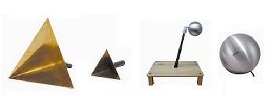
1.7. 76.5GHz RCS Quasi-Far Measurement System [RCS04] |
| |
This is a system which simply measures RCS (Radar Cross Section) at 76.5 GHz.
The RCS value is calculated from the dBm value of the target using a
corner reflector of an already - known RCS value as a reference point.
In conjunction with the rotating stage, the measurement can be performed
while rotating the target at any angle range. |
| |
Detail! |
2. Radar Cross Section (RCS) Measurement and Evaluation System / Tools for Evaluation
| |
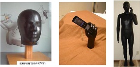
2.3. Silicone phantom (Silicon phantom) [EMA06] |
| |
Human body phantom for
・Driving test of collision avoidance radar,
・Development of radar system,
・Measuring specific absorption rate (SAR) of smart phone,
・Testing wearable communication tool.
The electric constant is in compliance with IEEE15528.
・We can also make it so that only the skin can be separated
・Easy to drill holes.
|
| |
Detail! |
3. RCS Simulation Software
| |
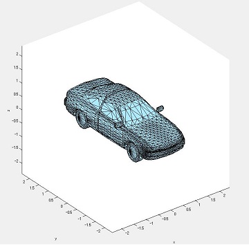
3.1. RCS Simulation Software (ACES) [SFW03] |
| |
KEYCOM has adopted PTD method, the best choice in RCS simulation of car, vessel, human body etc.,because of its high accuracy and fast calculation time.
In evaluating scattering of electromagnetic waves, KEYCOM improved physical-optical approximation (PO) method,realizing higher accuracy, shorter calculation time to be suitable for large targets. |
| |
Detail! |